They go by different nicknames—”George” and “Otto” probably are the most popular—and have become an integral part of even a basic IFR platform’s standard equipment, especially when flown single-pilot. And because the latest high-tech versions on the market can do just about anything for you except eliminate a potty stop, they’ve proliferated throughout all segments of the general aviation fleet. “They,” of course, are autopilots—electromechanical systems used to control an aircraft, and available in a wide variety of configurations and capabilities from simple wing-levelers to full-blown flight directors rivaling the modern transport jet you rode in last week.
Autopilots can function as a virtual copilot and—since we entrust to them control of the aircraft for hours at a time—it’s probably a good idea to consider how the various types are designed and deployed, along with their failure modes. Sophisticated autopilots used in meeting the common definition of technologically advanced airplanes (TAA) are capable of performing a myriad of flight tasks. Considered part of the aircraft’s avionics system, autopilots are designed to serve two basic purposes: enhance a pilot’s flight control capabilities and reduce cockpit workload by putting the airplane in an automatic flight mode. Let’s look at different autopilot systems, including a proposed classification system, and review some autopilot operating errors.

Basic Design
At a basic level, an autopilot is a control system applying actions based on measurements, using a negative feedback, closed-loop design. Negative feedback loops require a controller, and effector and receptor system components as illustrated in Figure 1 on the opposite page. It’s called “negative feedback” because the result of a certain flight condition inhibits further performance of that flight condition.
For example, suppose the pilot selects a heading of 360 degrees with the heading bug on a horizontal situation indicator (HSI) coupled to the autopilot. If the airplane’s heading temporarily deviates left to 355 degrees, it’s detected by the receptor and fed back to the controller which, in turn, inhibits this incorrect flight condition by commanding the effector/ailerons to bank the airplane to the right to the selected heading of 360 degrees. A closed-loop system operates continuously, many times per second, much more quickly and smoothly than a human pilot.
A single-axis autopilot operates only the ailerons to control flight along the longitudinal axis. It provides wing leveling, roll and heading control. Adding control of the elevators and the elevator pitch trim surface results in a two-axis system, controlling the lateral axis as well. In other words, roll, wing leveling, and heading control are combined with pitch and trim for altitude control (see Figure 2, at right). Add control of the rudder to yaw the aircraft about its vertical axis and the autopilot becomes a three-axis system. A yaw damper also may be fitted to smooth or dampen oscillations resulting from instability in the vertical axis, especially in turbulence.
Rate-Based? Or Attitude?
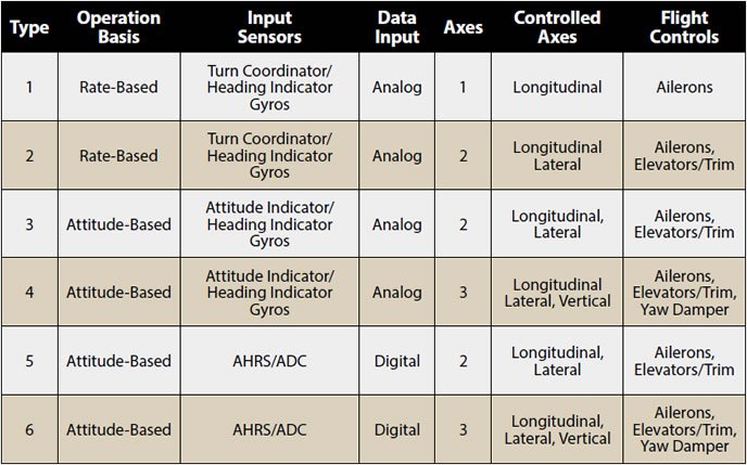
The two principal operating bases of autopilots for general aviation aircraft are rate-based and attitude-based systems. The variations in equipment among the various types are described in Table 1 below. An example of a rate-based, two-axis autopilot is the Bendix/King KAP 140, which may be classified as a Type 2 autopilot. Older style rate-based autopilot systems use analog data for their operation, i.e., information or data represented by continuously varying voltage or current. Typically, they get data from a turn coordinator and an altitude sensor.
An analog attitude-based or position-based autopilot uses output from a conventional attitude indicator gyroscope. The more modern, digital version uses an attitude heading and reference system (AHRS) and air data computer (ADC). Potentially, this type of autopilot is more precise than a rate-based example. A common rate-based autopilot is the Cobham (formerly S-TEC) 55X pictured above, which offers two-axis flight control. An example of an attitude-based, two-axis autopilot is the Avidyne DFC 90, which also is shown on above.

Output And Features
An autopilot issues output commands to the flight control surfaces via devices called servomotors or actuators. These mechanisms basically are electric motors that incorporate feedback so that the flight controls are correctly positioned. Servos are the “muscles” of an autopilot system.
For example, suppose while in the heading (HDG) mode the pilot desires to turn left by 90 degrees. After the heading bug is set to the desired heading on the HSI, the autopilot processes this information and then issues output commands to the aileron servomotors. As the servomotors move the left aileron “up” and the right aileron “down,” the autopilot monitors the progress of the turn via a closed-loop feedback system. Eventually, output commands from the autopilot stop when the AHRS for example signals that the aircraft is on the new pre-selected heading and signals wings level.
In some situations it may be advantageous to temporarily disable the servos from the autopilot with a function called control wheel steering (CWS). Pressing and holding the CWS button on the yoke temporarily disengages control outputs from the autopilot to servos, permitting the pilot to perform evasive maneuvers if needed in an emergency, for example, flying away to avoid a midair collision.
According to the NTSB, 40 percent of fatal fixed wing general aviation accidents occur because pilots lose control of their airplanes. Avidyne’s DFC 90 has safety features that may help prevent loss-of-control accidents. For a spatially disoriented pilot in instrument meteorological conditions, for example, a wings-level function helps to prevent an unusual attitude, perhaps one leading to a loss-of-control accident. In the event of needing to recover from an unusual attitude, the “straight and level” mode orients the airplane to wings-level flight.
All the pilot needs to do is push a panel-mounted button, and the autopilot does the rest: In the event airspeed is too high, an “overspeed” mode allows the autopilot to adjust pitch attitude as required to maintain VNE, thus preventing the airplane from exceeding maximal airspeed. In the event the airspeed is too slow, an “underspeed” mode allows the autopilot to adjust the bank angle and then pitch angle as required to maintain airspeed no lower than 1.2 VS.
In addition to its “straight-and-level” mode, Avidyne’s DFC 90, like other latest-generation digital autopilots, has other safety features. For example, its constant airspeed climb (IAS button) results in a constant-airspeed climb on departure, helping a pilot nail the airplane’s best rate of climb speed. Such a feature also helps prevent airspeed from eroding to critically low stalling speeds predisposing to a spin. The DFC 90, along with other autopilots, also incorporates a vertical-speed selection capability, allow constant climb or descent rates, necessarily with varying airspeed.
Failure Modes
As autopilots become more sophisticated and are tightly integrated into the aircraft’s electronic attitude, heading and air-data systems, their failure modes also take on greater sophistication. For example, failure of some Garmin G1000 components can cause the GFC 700 into reduced functionality or to become totally unusable. Because the PFD contains operational software for the flight director, failure of the PFD will disengage the GFC 700 autopilot, even though the G1000 will downgrade to its reversionary mode, i.e., its primary flight instruments are automatically displayed on the multifunction display (MFD).
Any failure of the following G1000 components also causes a complete failure of the GFC 700: AHRS, ADC, and integrated avionics unit (IAU) #1. If IAU #2 fails, only the flight director will function and the pilot must fly the aircraft by hand. If either of the GPS receivers within the two IAUs fails, there is no loss of autopilot functionality, as either GPS receiver can take over for the other one. If the MFD were to fail, IAU #2—which is directly connected to autopilot system components—fails with it. On some GFC 700 systems, the autopilot control panel is on the left side of the MFD, so failure of the MFD precludes the pilot from changing autopilot modes of operation and once the autopilot is disconnected it cannot be re-engaged.
Even if you’re not flying behind a G1000/GFC 700 combination, a failure elsewhere in your avionics system can render an autopilot inoperable, sometimes at the exact point when you need it most. A classic example involves older attitude-based autopilots, which require a working attitude indicator (AI) to work properly. In the event of a vacuum- or pressure-system failure, the AI will spin down, usually displaying an increasing bank angle. If the pilot fails to catch the failure and disengage the autopilot, bad things can happen quickly.
Of course, an electrical system failure can take out the entire avionics stack, and the autopilot with it. Usually. Older—antique, perhaps—autopilots like those made by Tactair and Brittain use vacuum and pressure systems, respectively, to spin gyros and move control surfaces, but no one suggests trying to revive one of these antiques just for immunity from electrical system failures.
Pilot Errors?
Given the wide variety of airframes, instrumentation and autopilots, it’s impossible to come up with a list of all kinds of errors pilots can make when operating autopilot systems. The sidebar on page 15 is a summary only, one that touches on some common errors pilots can make with any autopilot, even though they’re ones I’ve seen most often with the Garmin G1000/GFC 700 combination. So, we can only scratch the surface of errors pilots may encounter—or create—when using their autopilots.
Pilots should study their Pilot’s Operating Handbook or Airplane Flight Manual, as well as any autopilot-specific supplements or pilot’s guides from its manufacturer, to learn the autopilot’s operation and how it is integrated into the airplane’s other systems. Knowing how your autopilot works—and what other equipment it depends on for full and normal operation—can come in handy some dark and stormy night.
Dr. Banner is a flight instructor at University Air Center, Gainesville Regional Airport (KGNV), Gainesville Fla., professor at the University of Florida in Gainesville, and instructor pilot in the U.S. Air Force Auxiliary/Civil Air Patrol. A CFII, MEI, he has 5000 hours of flight time and owns a GCBC Citabria.


