
Heavier-than-air flight control systems can be as simple as shifting our weight around the center of gravity or as complicated as a full fly-by-wire arrangement where the cockpit controls have no mechanical connection to the moving surfaces. Early aviators copied the birds with wings of wax and feathers while others tried wing warping—and even flapping wings—none of which worked well.
When it was discovered that lift could be created by air flowing over a cambered surface, the technology took a giant leap forward. Along came the Wright Brothers, who experimented with flight controls and tried several designs and modifications to accomplish directional control in the vertical as well as the horizontal plane. Flight control was soon introduced in conjunction with aerodynamic surfaces that produced sufficient lift and control for extended flight. With these initial problems solved, aircraft development rapidly progressed to allow for faster and heavier aircraft.
Some More History
But as aircraft became faster and heavier, the effort required of the pilot became greater, with physical limitations and fatigue contributing to less-than-precise control of the aircraft. Weather conditions such as turbulence added to the pilot’s workload, and further increased the potential for accidents. Flight controls had to be designed to not only provide acceptable control forces for the pilot but also to protect the surrounding structure from damage in all flight regimes.
Engineers soon discovered that in larger, heavier or faster aircraft, some type of mechanical assistance was required to relieve the pilot of these heavy control forces yet protect the structure during operation. Different types of assistance were implemented, depending on the speed and weight of the aircraft. Engineers on some aircraft designs of moderate speed and weight utilized mechanical advantage to lessen the force required to control the aircraft, and this method is still in use.
A rather unique design was the control tab, where the tab was connected directly to the flight control system and the tab “flew” the control. This worked well and met most all the requirements but was not very pilot friendly, as there was some delay from the time the control input was initiated to the actual movement of the flight control and change in the aircraft’s trajectory.
Today, hydraulically operated or boosted controls on larger or higher-speed aircraft are the norm. The pilot manipulates the cockpit control, conveying the input instantly via hydraulic pressure to the individual actuators. The latest aircraft use the fly-by-wire system wherein the pilot’s control forces and feel, as well as flight control deflection, are primarily computer controlled.

Primary Controls
According to the FAA, primary controls are those “required to control an aircraft safely during flight” and include the rudder, ailerons and the elevator/stabilator of a conventional airplane. The method by which the aircraft is controlled varies the lift produced by each aerodynamic surface. In small airplanes like you and I fly, the ailerons, rudder and elevator/stabilator are controlled by cables or push rods routed to the pilot’s control stick or yoke, and to the rudder pedals. In addition to these primary controls, secondary controls such as movable trim tabs, primarily used to assist in adjusting pitch control, or fixed trim tabs are used to lessen rudder and aileron control forces.
Ailerons mounted near the wingtip provide efficient control about the longitudinal axis or roll. When one aileron is deflected upward to decrease lift and lower the wing, the opposing aileron is deflected downward a different amount—to reduce adverse yaw—to increase lift and raise the wing.
Rudder movement is concerned with lift as a horizontal component, and yaws the air plane about its vertical axis. Coordinated flight requires both rudder and aileron input, and we always should be reminded that improper use of the rudder at low speeds can lead to a spin. Elevators or stabilators are attached to the rear of the fuselage, and decrease or increase lift as a result of fore and aft control yoke or stick movement to control pitch.
What about wing flaps, spoilers and other devices? They’re generally referred to as secondary flight controls, too, though spoilers may be a primary method of controlling roll in some designs.
Trim, one of the secondary flight controls, can be used in a pinch to manage the airplane’s pitch attitude if the primary system fails. Trim in any axis helps relieve control pressures and uses smaller surfaces producing less drag when deflected to handle small-scale flight-path corrections in cruise, for one example. Mooneys apply pitch trim by moving the entire empennage—changing the horizontal stabilizer’s angle of incidence.
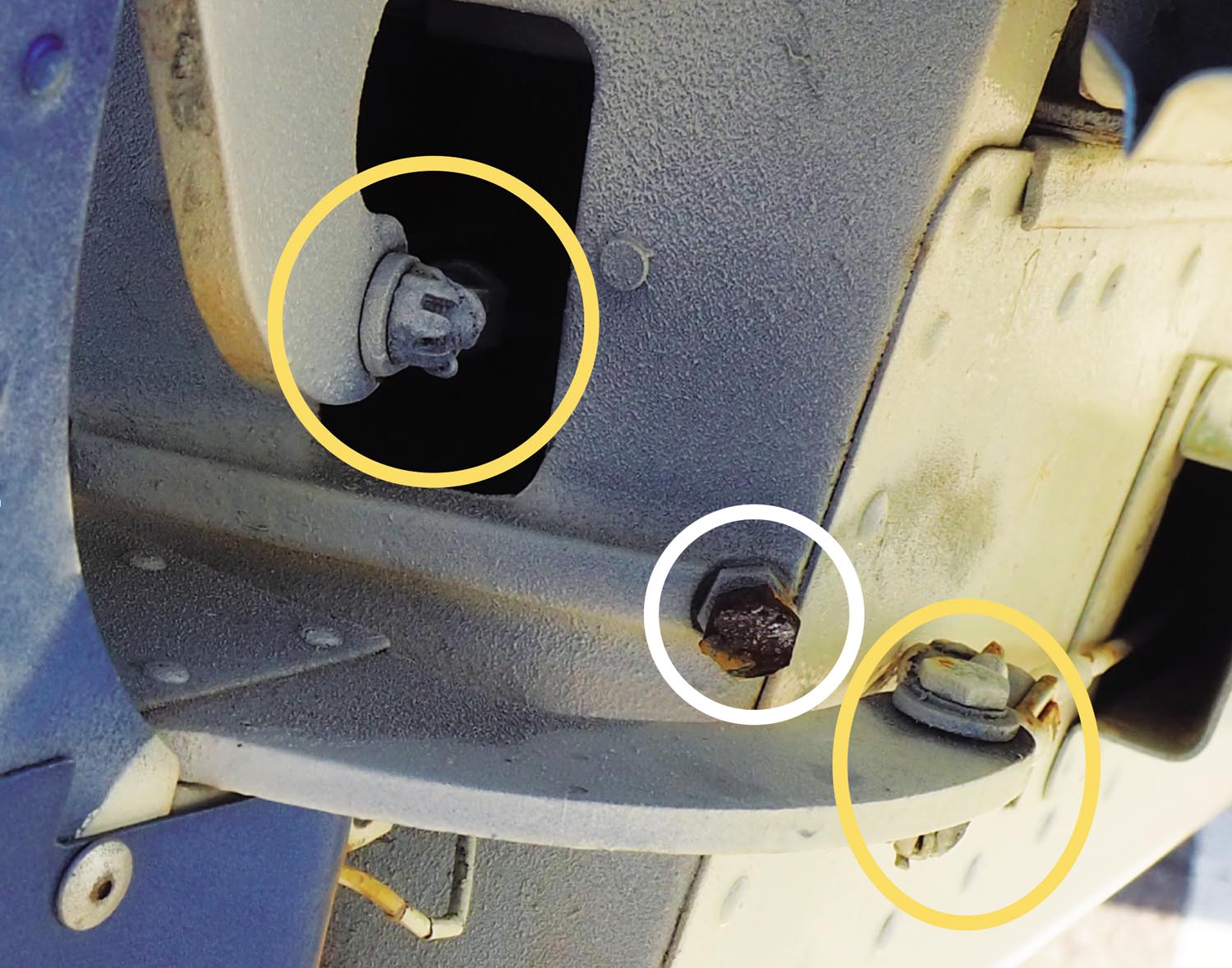 Circled in white is the rudder limit stop. Airworthiness Directive 2009-10-09 R2, September 2011, applied to many models of Cessna’s 150 and 152 concerning the rudder getting jammed at full deflection by the stop mechanism. One corrective action includes installing modification kits: P/N SK152-24A or P/N SK152-25A).
Failure Modes
Control system failures happen, though they’re rare. In personal airplanes, neglect and old age often are to blame when a cable jams or breaks, a pushrod corrodes or a hinge fractures. Hangar rash certainly can be a factor with the control surfaces themselves. But the principal control-surface failure modes has nothing to do with wear and tear.
The failure generally will fall into one of four areas:
- jammed cable or pushrod, where the control surface can’t be moved from the cockpit;
- broken cable or pushrod, where the surface is completely disconnected from its actuating system;
- installation error, like reversing the aileron cables;
- broken hinge or other component unrelated to the control system itself.
Once properly installed and regularly inspected, the control surface system rarely needs attention. Keep the pulleys clean and lubricated (but not the cables!) and the systems generally are trouble-free. Until someone messes with them, that is.
Errors by maintenance personnel and pilots alike have contributed significantly to control surface issues. Mistakes range from rigging flight controls in reverse, failing to remove gust locks, improper lubrication and not following recommended inspection methods and repair procedures. Once, while removing a tail cone to replace a VOR antenna, I discovered a bolt with no nut that connected the flexible up elevator cable to the up-elevator bell crank. It likely had been disassembled at some point and a self-locking nut installed. In fact, self-locking nuts should never be used in flight-control applications, as discussed above.
Other failure modes include worn control cables—sometimes just a few broken strands is all it takes. The flight control cables themselves consist of steel wire strands grouped together with small-diameter wires, sometimes known as wire rope. A cable identified as 7 by 7 consists of six strands of seven wires each laid around a center strand of seven wires providing for a flexible but strong cable.
Careful inspection of cables and all associated components for wear, corrosion and tension should be done at each 100-hour or annual inspection. A single broken strand of wire is cause for replacing the entire cable.
Last Line Of Defense
Pilots are the last line of defense against control system failures. During preflight, all surfaces should be secure, and move freely and quietly. Once aboard, confirm your input results in the chosen control surface moving in the desired direction. Any concerns about your flight control system should be addressed by a qualified technician prior to flight.


