Early in our primary training, we encountered the concept of maneuvering speed (VA), or design maneuvering speed as it’s sometimes called. We’re basically told it’s the speed at below which we should fly in turbulence and when entering advanced maneuvers, hence its name. If we’re lucky and have a good ground-school instructor, we’ll also learn that VA changes with weight: As the airplane’s weight decreases, so will maneuvering speed. Although VA isn’t marked on our airspeed indicators, there should be a placard listing it at the airplane’s gross weight, with the admonition to not make full control deflections above it.
Out in the practice area, VA often is used as the target speed for entering maneuvers like accelerated stalls, chandelles and lazy eights, although some manufacturers may publish a different speed. Basically, when we’re engaged in maneuvers imposing additional loads on the airframe, we should be flying at or below the airplane’s weight-adjusted VA. But that’s not the full story. Some of the things we’re not told about VA in ground school are learned the hard way.
Background
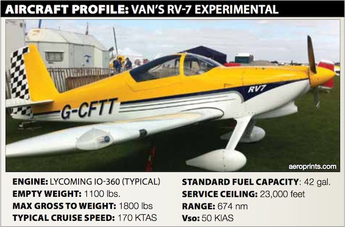
On December 10, 2015, at about 1347 Mountain time, an experimental Van’s RV-7 homebuilt experienced an in-flight breakup and impacted terrain in Hurricane, Utah. The airline transport pilot and passenger were fatally injured; the airplane sustained substantial damage. The airplane was registered to the pilot. Visual conditions existed.
Several witnesses heard the airplane’s engine make what sounded like power changes. One witness observed the airplane spiraling and descending in a corkscrew-type maneuver. Other witnesses reported observing pieces of the airplane “floating in the air.”
The accident site was located between a cold front to the northwest and a high-pressure area to the southwest, in an area of strong pressure gradients. The wind profile of a weather model for the accident site estimated the surface horizontal wind was from 220 degrees at eight knots, with winds increasing in speed with height and veering west. The model supported light-to-moderate clear air turbulence from 6400 feet msl through 8000 feet, and mountain wave development from 10,000 to 12,000 feet msl. Pilot reports noted mountain wave activity in the region with moderate-to-severe turbulence near the accident site. An Airmet for moderate turbulence below 18,000 feet was active over the accident site at the accident time.
Investigation
The debris path was about 1460 feet long and 450 feet wide. All major components of the airplane were located in the debris path. The main wreckage included the fuselage, engine, right wing, half of the left wing, a majority of the left and right elevators and the lower half of the rudder. The vertical stabilizer with the upper half of the rudder still attached was located about 1420 feet away. The left and right horizontal stabilizers were located about 850 feet and 790 feet, respectively, from the main wreckage. The left aileron was about 430 feet away from the main wreckage; the left outboard wing was located about 320 feet from the main wreckage.
The engine revealed no evidence of mechanical malfunctions or failures that would have precluded normal operation.
The outboard half of the right wing was deformed downward about 15 to 20 degrees at the flap/aileron junction. The upper and lower wing skins were buckled around the area where the wing was deformed downward. The outboard half of the left wing also had separated at the flap/aileron junction. The left wing’s main spar had fractured where the upper and lower spar caps undergo a net section decrease from inboard to outboard. The outboard half of the left wing was mostly intact with minimal damage noted. Examination of the wing fracture locations revealed damage and deformation consistent with the separation of the outboard portion of the wing in a downward direction.
The horizontal stabilizer forward spar fractured about two inches outboard of the fuselage on both sides. Both of the horizontal stabilizer spar caps were deformed down and aft at the fracture location. The elevators were deformed down and aft matching the spar deformation. There was buckling damage on the lower skin of both horizontal stabilizers consistent with the stabilizers separating downward.
All fractures exhibited a dull, grainy appearance consistent with overstress separation. There was no evidence of progressive or pre-existing fractures on any of the parts.
No data for the accident flight was recovered from the electronic devices found in the wreckage. However, a video camera contained two files recorded on previous flights in which the accident airplane performed an aileron roll to the right.
Commercially available radar data revealed two tracks consistent with the accident airplane. One track was 17 minutes long and ended at 1332 when the airplane was at 6150 feet msl. Altitudes throughout the track varied from 6150 to 9350 feet, and groundspeed varied between 24 and 168 knots.
Although the airplane’s most recent weight and balance records were not located, an estimated weight and balance was calculated using the airplane kit manufacturer’s data. Presuming a total fuel load of 42 gallons, the airplane would have been about 128 lbs below its maximum gross weight of 1800 lbs at the time of the accident.

Probable Cause
The NTSB determined the probable cause(s) of this accident to include: “The pilot’s abrupt flight control inputs, likely above the maneuvering speed, in severe winds and turbulence conditions, which resulted in an in-flight breakup.”
Based on the aircraft’s radar track, the pilot was maneuvering the airplane, perhaps including aerobatics. The NTSB’s probable cause finding combines the G-loading effects of those maneuvers with the atmospheric conditions forecast to exist and concludes the aircraft encountered a wind gust that combined with the G-loading to impose on the airframe loads in excess of its design.
In other words, abrupt maneuvering in turbulent conditions can risk exceeding the airplane’s structural limitations. According to the FAA’s Airplane Flying Handbook (FAA-H-8083-3B), VA is based on the wing’s response to a 50-fps gust or elevator movement. Combining turbulence and high G loading induces even greater stress on the aircraft.
American Airlines Flight 587
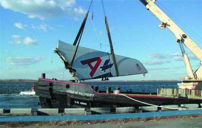
On November 12, 2001, an Airbus A300 operating as American Airlines Flight 587 departed John F. Kennedy International Airport for the Dominican Republic. Shortly after takeoff, it encountered wake turbulence from a 747 that took off ahead of it. The first officer/pilot flying made a series of aggressive, alternating rudder inputs in an attempt to stabilize the airplane. However, his control inputs were so aggressive that the airplane’s vertical stabilizer, pictured at right, broke off the airframe and fell into Jamaica Bay.
The NTSB determined the vertical stabilizer failed, in part, after loads beyond its ultimate design were created by the first officer’s rudder input, even though the airplane was well below its maneuvering speed (VA) at the time. Prior to the AAL587 crash, pilots had been trained that any abrupt control input made below VA would not break the airplane.
After that accident, definitions like the following from the FAA’s Airplane Flying Handbook (FAA-H-8023-3B) were revised to reflect that design requirements do not consider repeated control inputs: “The structural design requirements do not cover multiple control inputs in one axis or control inputs in more than one axis at a time at any speed, even below VA. Combined control inputs cause additional bending and twisting forces.”


