Bolts, screws, rivets and skin—they keep all the parts flying in formation. When they are properly tightened and well fitted, with metal specifications, thread pitches and torques all carefully considered, you and your aircraft parts should land simultaneously.

Despite the best care of aircraft designers and mechanics, however, aviation does not always proceed according to expectation. Component failure, the culmination of repeated stresses known as metal fatigue, can mean you and your parts landing in different locations, a situation best avoided.
Why Metal Fails
Metal does not lose strength with age. In fact, an old part can be just as strong as a new one. Under the right—or wrong—conditions, any metal part will break. Aircraft designers do a good job of specifying the right materials and parts to withstand normal loads. They include significant safety margins, so metal parts rarely fail while operating within their design limits. But not all operations stay inside that envelope. Improper fit, vibration causing fasteners to shift or loosen, incorrect tightening or repeated overstress are all conditions that can bring metal parts to the point of failure.
To keep such failures from ruining your day, it’s important to have some basic understanding of metals’ properties. Perhaps the most useful for understanding metal fatigue are tensile strength (the resistance to being pulled apart) and elasticity (the tendency to return to an original shape after a distorting force is removed). When a metal component’s tensile strength is exceeded, it elongates until it breaks. When a metal component is stressed beyond its elastic limit, it will bend out of shape and become deformed.
The physics of most metal failure starts at the molecular level. All metal, even newly forged steel, has microscopic imperfections, invisible flaws. As metals are stressed, they deform and small imperfections driven by load cycles can cascade through the system and amplify. The effect is similar to the traditional accident chain: one problem leads to another. A crack will not spontaneously grow, but if you add a deforming stress and then repeat that stress, each load cycle will give a microcrack or a nick a chance to grow. In the case of a landing gear bolt, for example, the more landings and takeoffs there are, the more cycles the bolt has to bear.
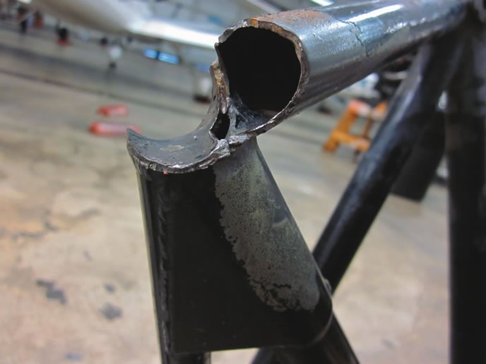
Sometimes microcracks will hit a void spot or other imperfection in the metal and stop growing. Stop-drilling a crack can mimic this natural healing process. Other times, networks of microcracks in a stressed area will join together, causing a little crack to grow further, perhaps becoming a visible one. My landing gear bolt (see the images on this page and accompanying text) may have had a manufacturing defect, or perhaps it was over-tightened at installation. Based on the oxidation pattern, I suspect the 182 to which it was attached must have suffered a hard landing or two years before I took ownership. My suspicions have always been that airplane’s landing gear had sustained an excessive side load, causing the initial crack to form.
Once it originated, the crack continued growing with repeated cycles of loading and unloading the gear. At some point, a landing created enough stress to exceed the elastic limit of the remaining metal cross section. The bolt head bent, changing the tension in the system, which presented as landing gear vibration. The remaining landing gear saddle bolts now had a bigger job as the load among them no longer was balanced as designed. At the same time, the new vibration subjected the system to additional stress.
The Good News
Metals behave predictably, even those with invisible flaws. A metal of a given cross-section will bend or shear exactly as it is supposed to, following a statistically predictable curve. Engineers take these predictable properties into account when designing aircraft. They choose each part to have both the right tensile strength and elastic limit to perform its intended function, which might be attaching the engine to the airframe, the propeller to the engine or the wing to the fuselage. Every bolt has a design spec to ensure it reliably performs its duties under the expected load conditions. The next time you enjoy the miracle of flight, be sure to tip your hat to an engineer.
With ferrous metals like iron and steel, there is a loading below which no appreciable fatigue occurs. In other words, if the bolt is big enough, it won’t bend or break. This fatigue limit is around a third to a half of the tensile strength, depending on the alloy. Aluminum, on the other hand, does not have a fatigue limit. Instead it has a steady curve of accumulated fatigue.
For all metals, however, there is a point where repeated applications of stress—a loading and unloading cycle—will lead to failure. The stress curve or fatigue limit is found by repeating millions of loading/unloading events on a sample to generate a stress curve of calculated cycles-to-failure. This predictability enables engineers to size a bolt to withstand the expected stresses of its location and duty, and bring known weaknesses to our attention.
One particular way metals are optimized for performance is preloading stress. This is why torque values are specified on critical components subjected to high stress, like cylinder head bolts and propeller lugs. Proper torque ensures the metal holds the load according to its design. So if everything is designed to stay within limits, why do parts fail?
The simple answer is nothing, not even a new part, is perfect. Fortunately, aircraft manufacturers and mechanics know a great deal about where to anticipate metal fatigue and cracking in specific airframes. Together with pilots, mechanics can keep an eye on metal fatigue “hot spots” during routine inspections and pay particular attention after pilots disclose overloading events like hard landings, violent encounters with turbulence or other non-routine stress.
Design for Fatigue
Engineers don’t just pick a screw, nut or rivet size arbitrarily. They design parts—including the type of metal and size—to ensure the potential for failure is well below the stress produced by specified limits in the aircraft design. Oversizing load-bearing parts could minimize metal fatigue, but alas, airplanes must fly, so parts are optimized so they can handle designed levels of stress while having a minimal impact on weight. Finding the sweet spot is a balancing act that keeps aeronautical and structural engineers employed.
This is why owners and mechanics must be picky about using parts and components matched to their aircraft. It is not a good idea, nor is it legal, to pick up similar-looking screws and bolts at the local hardware store. For certified aircraft, a designated part number is required to match a mechanical engineering specification.
If aging aircraft components are found to be problematic, the FAA has processes to flag concerns. The g-loading and weight-hauling requirements specified by manufacturers in the type certificate data sheet keep an aircraft inside a conservatively bounded envelope, ensuring the aircraft parts all remain in close formation while flying under expected certified conditions. The final certified design is basically a testament that a given combination of parts will remain in that formation when flown within the specified operating envelope.
Older Aircraft
The FAA issues airworthiness directives (ADs) to owners and operators of affected airplane model types, engines, propellers or appliances, such as instruments, to correct an unsafe condition. The required actions usually include modifications or replacement with an improved part, one-time inspections, repetitive inspections or some combination.
For older aircraft, the list of ADs provides an immediate listing of critical parts or systems that are either prone to wear or failure. If you are worried about metal fatigue on an older aircraft, the AD list will give you a quick insight into where stresses and strains might present themselves on your airframe and powerplant.
A major part of an annual inspection is ensuring any applicable ADs have been complied with, which requires a logbook entry indicating the same. The problem with logbook entries is that all mechanics may not be equally rigorous. Some may be under pressure to provide a quick or cheap annual. When you see the phrase “All ADs complied with” in a logbook, it could well be true, or it could just be a lazy way of pencil-whipping the airplane out the door. It is always more reassuring to see a list of each applicable AD along with a note stating the actions taken by the mechanic to achieve compliance.
Similar to an AD but not regulatory in nature are Special Airworthiness Information Bulletins (SAIBs), which provide information regarding less serious airworthiness issues. A SAIB may reference a manufacturer service bulletin or service letter for a given airframe or power plant. You can access both ADs and SAIBs on the FAA’s Web site: rgl.faa.gov.
Most aircraft accidents result from operator error, not part failure, but there are exceptions. The flight history of an aircraft (like your last hard landing) is worth paying attention to.
Early Detection
The best place to detect impending part failure is on the ground during a preflight or annual inspection. If your aircraft starts to vibrate, shimmy or do the Harlem shake while in flight, you may need to take urgent action, like finding the nearest airport or field for a precautionary landing.
If you think the vibration or noise indicates a chronic (rather than acute) problem, you might choose to take some time in the air to do further analysis, but only if you decide it seems safe to do so. Change flight parameters and try to isolate the source of the noise or vibration as best you can. Any change from normal will have a root cause, and come with a high likelihood that metal fatigue or a missing part is the culprit.
Mike Hart is an Idaho-based commercial/IFR pilot with more than 1100 hours, and proud owner of a 1946 Piper J3 Cub and a Cessna 180. He also is the Idaho liaison to the Recreational Aviation Foundation.


